Edirol SD-90
Edirol SD-90 – Brief tour of the Editor.
The SD shares the same patch, voice and tone naming fad as the Fantom XR, “tones” make up “patches”, thus, voices and tones to us are tones and patches to it, the remaining fundamentals do not alter.
The software supplied with the SD90 only acknowledged to the synthesiser’s GM2 sound banks and harboured no timbrel tailoring facilities. To gain access to its rich and radical repertoire of native tonality, it was necessary to use the editing application primarily attributed to its spiritual and physical half brother, the SD80.
Fortuntely, the ROMS under their respective roofs were identical, with the SD90’s only enhancement being its aptitude to serve as a conventional sound card and combine its virtuous vocals with a collection of digital effects.
At first glance, the program reveals a very similar GUI to that of the Fantom XR and despite not featuring separate Performance and Patch modes, all of its comprising patches (tones) can be edited and refined on a tone (voice) specific basis in exactly the same fashion.
As soon as the initial screen appears, clicking on the “part survey” button will call up a crucial control panel presenting an overview of the fundamental settings applicable to each part, including its prescribed patch, settings for reverb chorus and delay, output assign and a switch to direct the patch through one of the unit’s three multi FX engines (A, B or C).
The “output assign” knob is crucial and controls where the part and its applicable patch is being routed.
A single click on the “Edit” button of any part will activate the “Patch Edit” strip for that part and it’s initialized patch, from which all the settings pertaining to the patch and the tones it is compiled from can be accessed.
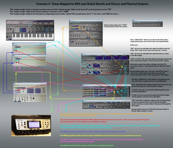
One click on the button inscribed “Patch TVA” will initiate the “Patch TVA” console where detailed settings specific to the patch’s compositional tones can be customised. The TFA and LFO consoles also apply here, though as with the Fantom, the TVA fosters additional faders for dry signal, reverb and chorus sends and “output assign” allocated to each of the patch’s underlying tones. As the SD-90’s editor has no “FX routing” screen, this is of as it is the only way to route a patches separate elements either directly to an output or to one via the MFX engine.
Pressing the “Patch Common” button will bring up the “Patch Common” control panel.
This also has a slider entitled “output assign” which is used to determine the ultimate destination of the patch (tone) and the tones (voices) that it encompasses.
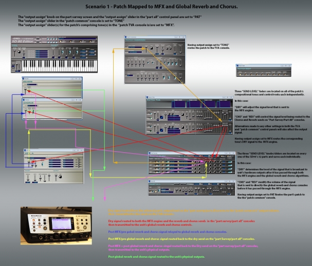
When set to “Tone”, the patch or played sound is referred to the “patch TVA” console.
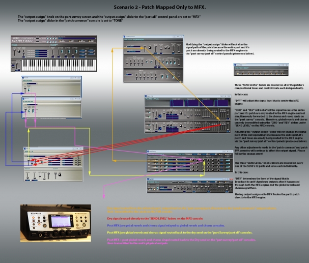
When the slider set to MFX, the entire patch is mapped directly to the multi effect selected for that part on the “part survey” console (either A, B or C) which can then be combined with the unit’s communal chorus and reverb effects via the applicable MFX console .
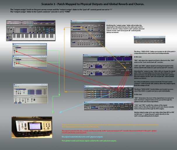
When set to any other value (1, 2, 1r, 1l, 2r, 2l) the patch/audio signal bypasses the MFX engine and is transmitted directly to the unit’s physical outputs.
Parameters relating to the selected multi effect MUST initially be dictated using their respective control panels. Once again, these are accessed on the applications main screen by clicking the blue buttons next to “param”and under “mfx” and rev”
Similarly, granularity, type and texture of reverb and chorus must first be defined in the global reverb and chorus consoles. These are accessed on the applications main screen – the one with the virtual keyboard – by clicking the blue buttons next to “param” and under “cho” and rev”.
The “part survey screen” together with the “part all” screen on the sd-90 should be treated the same way as the “fx routing” control panel on the Fantom XR.
For example, on the part survey screen, when the dial under “output assign” for any part is set to a value other than “PAT” (patch) the “output assign” faders in both the “Patch TVA” console AND the “Patch Common” control panel are bypassed as the entire patch and hence, its full mix of voices are being mapped either directly to an output, or to one via the MFX processor.
Moreover, if the dial is set to “MFX”, the knobs/sliders for “chorus” and “reverb” on the “part all” and “part survey” screens no longer affect the output signal.
These diagrams are intended to illustrate the signal path(s) that a patch will be assigned when applying four different combinations of settings.
Only one of the three MFX engines (A B or C) can be applied to a particular part, though all three can serve alternate parts concurrently.
Contrary to the Fantom, it would appear the SD90 only possesses the facility to route patches (tones) and tones (voices) either directly to its primary physical outputs as two channel signal and/or to them via the MFX processor. It cannot allocate patches or individual tones to its secondary outputs or to specific left or right channels its primary outputs, despite the relevant controls being provided.
Pages: 1 2


